- Navigate to Devices -> Device Management, right-click on the SRX and select Device Configuration -> Modify Configuration -> Security Logging

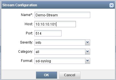
- Set the mode to Stream (better for performance on the branch SRX and required on the high end SRX), the source address should be the IP address of the SRX, and the format should be sd-syslog
- Click on the green "+" icon to add a new stream configuration
- Select Deploy and review the configuration changes to be deployed
- Select Approve and then Deploy
- Click on the job to verify successful deployment
Monday, October 12, 2015
Junos Space Security Director - Part IV
Tuesday, September 22, 2015
Junos Space Security Director - Part III
The third part of this guide demonstrates how to import an SRX series firewall into Junos Space (version 14.1R3.4). It assumes that Junos Space, Security Director, and a Log Collector are already deployed and operational. For steps on how to install Junos Space components, start here.
- In Security Director, navigate to Devices and select Click here to Discover Devices.
- Follow the prompts to add a device target. In this example, we will add the SRX via its IP address.
- Continue to follow the prompts to add options like ping, SNMP, and SSH as methods to discover the device.
- Select Discover. Upon completion a status page will be displayed showing success.

- Navigate to Security Director Devices to verify configuration/connection status, and the schema version in use.
- If the schema version is out of date:
- Navigate to Network Management Platform -> Administration -> DMI Schemas -> Update Schema
- Select SVN Repository and then Configure
- Enter https://xml.juniper.net/dmi/repository/trunk/ for SVN URL
- Enter your Juniper Networks support credentials
- Test the connection and then save
- For Device Family select junos-es
- Click Connect
- Select the Junos version that matches the version installed on the SRX and click Install
- Once installed, navigate back to Network Management Platform -> Administration -> DMI Schemas, select the OS version recently installed and then under actions select Set as Default Scheme
- Navigate back to Security Director -> Security Director Devices to verify that the correct schema version is showing

- Right-click the device and select Import
- Select the policies to import (in this case we would import both NAT and Firewall policies, and click Next
- A summary will be shown listing the configuration elements to be imported. Click Finish.
- A summary will be shown listing the configuration elements that were imported. Click Close.
- Navigate to NAT Policies, right-click on the SRX host name and select Assign Devices
- Select the SRX host name and then select Modify
- In NAT Policies, right-click the on the SRX host name and select Publish NAT Policy
- Click Publish and then verify that it was successful

- Navigate to Firewall Policies, right-click on the SRX host name and select Assign Devices
- Select the SRX host name and then select Modify
- In Firewall Policies, right-click the on the SRX host name and select Publish Policy
- Click Publish and then verify that it was successful

- To test things out, navigate to Firewall Policies, click on the SRX, and then click on the green lock to edit.
- Modify or create a policy (in my case, I changed an existing policy's action from permit to deny)
- Click Save and the right-click the SRX and select Publish
- Click on Publish and Update
- Verify that the update was successful by viewing the job status and/or doing a show | compare from operational mode in the CLI
- Don't forget to revert your change after testing is complete :)
Wednesday, September 2, 2015
Junos Space Security Director - Part II
The second part of this guide demonstrates how to add the Log Collector subsystem to Junos Space (version 14.1R3.4). It assumes that Junos Space and Security Director are already deployed and operational. For steps on deploying Junos Space and Security Director, see this post.
- Download the Log Collector OVA image from the Juniper Networks support site.
- Install the Log Collector image in your virtual environment. Refer to this Juniper document for details on how to size things.
- Upon starting the VM, enter the following credentials:
- root
- juniper123
- Change the password.
- Follow the prompts to configure the following settings:
- Configure IP address
- eth0 pulls a dynamic address, which you can change to a static (i.e. 10.10.10.6)
- eth1 is statically set by default. You can leave this alone.
- Configure time zone
- Configure name server settings
- Configure ntp settings
- Quit
- In Junos Space, navigate to Administration -> Fabric, and select the green button to add a fabric node.
- Name the node, type the IP of the collector, check the Add as a specialized node option, and enter the login credentials.

- Check the job status under Jobs -> Job Management.
- Once complete, log out and then log in again.
The next post will show you how to import and manage an SRX series firewall, and begin logging traffic.
Tuesday, September 1, 2015
Junos Space Security Director - Part I
The first part of this guide demonstrates the initial deployment of Junos Space and Security Director (version 14.1R3.4) in a virtual environment.
- Download the Junos Space (OVA) and Security Director (IMG) images from the Juniper Networks support site.
- Install the Junos Space image in your virtual environment. Refer to this Juniper page for details on how to size things.
- Upon starting the VM, enter the default credentials:
- admin
- abc123
- Change the password.
- Select "S" to install Space.
- Configure the interface for eth0 to be used for management access (i.e. 10.10.10.5)
- Configure the interface for the GUI (i.e. 10.10.10.100)
- Junos Space will then be deployed, with the GUI showing the following:
- Upon completion, enter the following credentials:
- super
- juniper123
- Change the password.
- Login using the new password.
- Navigate to Administration -> Applications to add an application (green button).

- Upload the Security Director image via HTTP.
- Select the Security Director image that was previously uploaded and click Install, then OK.
- Note - If you navigate away from the upload page, you will have to navigate back to Administration -> Applications and click the green button again to see the uploaded application.
- Navigate to Jobs -> Job Management to check the status of the install.
- Once complete, log out and then log back in, and then navigate to Administration -> Applications to look at what was installed.


The next post will show how to add the Log Collector subsystem to Junos Space.
Wednesday, August 26, 2015
VPN Between a Dell SonicWALL and a Juniper Networks SRX
I have seen multiple people in
forums asking how to setup a site to site VPN between a Juniper SRX
firewall and a Dell SonicWALL firewall. I originally created this post to provide the steps to get things working. I noticed while working with a client that following the old steps no longer work. Below are the revised steps that I took to
get it working, and is based on the following topology:

First we will configure the SRX:
Configure Interfaces:
set interfaces ge-0/0/0 unit 0 family inet address 10.10.10.2/30
set interfaces ge-0/0/1 unit 0 family inet address 192.168.1.1/24
set interfaces st0 unit 0 point-to-point family inet
Configure Routing:
set routing-options static route 172.16.1.0/24 next-hop st0.0
set routing-options static route 0.0.0.0/0 next-hop 10.10.10.1
Configure VPN Parameters:
set security ike policy SRX-TO-SW mode main
set security ike policy SRX-TO-SW proposal-set standard
set security ike policy SRX-TO-SW pre-shared-key ascii-text thisismypsk
set security ike gateway SRX-TO-SW ike-policy SRX-TO-SW
set security ike gateway SRX-TO-SW address 11.11.11.2
set security ike gateway SRX-TO-SW external-interface ge-0/0/0.0
set security ipsec policy SRX-TO-SW proposal-set standard
set security ipsec vpn SRX-TO-SW bind-interface st0.0
set security ipsec vpn SRX-TO-SW ike gateway SRX-TO-SW
set security ipsec vpn SRX-TO-SW ike proxy-identity local 192.168.1.0/24
set security ipsec vpn SRX-TO-SW ike proxy-identity remote 172.16.1.0/24
set security ipsec vpn SRX-TO-SW ike proxy-identity service any
set security ipsec vpn SRX-TO-SW ike ipsec-policy SRX-TO-SW
set security ipsec vpn SRX-TO-SW establish-tunnels immediately
set security flow tcp-mss ipsec-vpn mss 1350
Configure Security Zones:
set security zones security-zone UNTRUST interfaces ge-0/0/0.0
set security zones security-zone UNTRUST host-inbound-traffic system-services ike
set security zones security-zone TRUST interfaces ge-0/0/1.0
set security zones security-zone TRUST host-inbound-traffic system-services all
set security zones security-zone TRUST host-inbound-traffic protocols all
set security zones security-zone VPN interfaces st0.0 host-inbound-traffic system-services all
set security zones security-zone VPN interfaces st0.0 host-inbound-traffic protocols all
Configure Security Policies:
set security policies from-zone TRUST to-zone UNTRUST policy TRUST-TO-UNTRUST match source-address any
set security policies from-zone TRUST to-zone UNTRUST policy TRUST-TO-UNTRUST match destination-address any
set security policies from-zone TRUST to-zone UNTRUST policy TRUST-TO-UNTRUST match application any
set security policies from-zone TRUST to-zone UNTRUST policy TRUST-TO-UNTRUST then permit
set security policies from-zone TRUST to-zone VPN policy TRUST-TO-VPN match source-address any
set security policies from-zone TRUST to-zone VPN policy TRUST-TO-VPN match destination-address any
set security policies from-zone TRUST to-zone VPN policy TRUST-TO-VPN match application any
set security policies from-zone TRUST to-zone VPN policy TRUST-TO-VPN then permit
set security policies from-zone VPN to-zone TRUST policy VPN-TO-TRUST match source-address any
set security policies from-zone VPN to-zone TRUST policy VPN-TO-TRUST match destination-address any
set security policies from-zone VPN to-zone TRUST policy VPN-TO-TRUST match application any
set security policies from-zone VPN to-zone TRUST policy VPN-TO-TRUST then permit
Configure NAT:
set security nat source rule-set TRUST-TO-UNTRUST from zone TRUST
set security nat source rule-set TRUST-TO-UNTRUST to zone UNTRUST
set security nat source rule-set TRUST-TO-UNTRUST rule SRC-NAT match source-address 192.168.1.0/24
set security nat source rule-set TRUST-TO-UNTRUST rule SRC-NAT then source-nat interface
Next we will configure the TZ:
Enable and add a VPN:
Navigate to VPN->Settings, and then check the box to enable VPN and then click Accept.

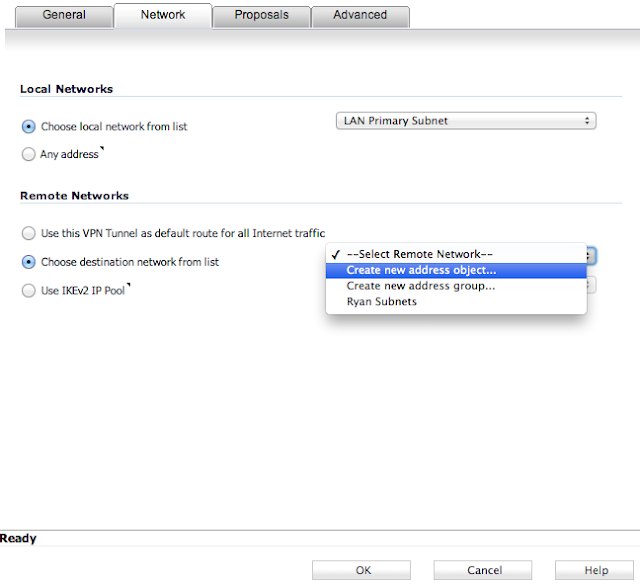
Add a new VPN by selecting Add... under VPN Policies on the same page. Enter parameters as shown in the subsequent screenshots for each tab, and then click OK.


 That's
really it. You can then enable or disable the VPN on the SonicWALL at
any time via a checkbox next to the newly created VPN on the VPN->Settings page.
That's
really it. You can then enable or disable the VPN on the SonicWALL at
any time via a checkbox next to the newly created VPN on the VPN->Settings page.

First we will configure the SRX:
Configure Interfaces:
set interfaces ge-0/0/0 unit 0 family inet address 10.10.10.2/30
set interfaces ge-0/0/1 unit 0 family inet address 192.168.1.1/24
set interfaces st0 unit 0 point-to-point family inet
Configure Routing:
set routing-options static route 172.16.1.0/24 next-hop st0.0
set routing-options static route 0.0.0.0/0 next-hop 10.10.10.1
Configure VPN Parameters:
set security ike policy SRX-TO-SW mode main
set security ike policy SRX-TO-SW proposal-set standard
set security ike policy SRX-TO-SW pre-shared-key ascii-text thisismypsk
set security ike gateway SRX-TO-SW ike-policy SRX-TO-SW
set security ike gateway SRX-TO-SW address 11.11.11.2
set security ike gateway SRX-TO-SW external-interface ge-0/0/0.0
set security ipsec policy SRX-TO-SW proposal-set standard
set security ipsec vpn SRX-TO-SW bind-interface st0.0
set security ipsec vpn SRX-TO-SW ike gateway SRX-TO-SW
set security ipsec vpn SRX-TO-SW ike proxy-identity local 192.168.1.0/24
set security ipsec vpn SRX-TO-SW ike proxy-identity remote 172.16.1.0/24
set security ipsec vpn SRX-TO-SW ike proxy-identity service any
set security ipsec vpn SRX-TO-SW ike ipsec-policy SRX-TO-SW
set security ipsec vpn SRX-TO-SW establish-tunnels immediately
set security flow tcp-mss ipsec-vpn mss 1350
Configure Security Zones:
set security zones security-zone UNTRUST interfaces ge-0/0/0.0
set security zones security-zone UNTRUST host-inbound-traffic system-services ike
set security zones security-zone TRUST interfaces ge-0/0/1.0
set security zones security-zone TRUST host-inbound-traffic system-services all
set security zones security-zone TRUST host-inbound-traffic protocols all
set security zones security-zone VPN interfaces st0.0 host-inbound-traffic system-services all
set security zones security-zone VPN interfaces st0.0 host-inbound-traffic protocols all
set security policies from-zone TRUST to-zone UNTRUST policy TRUST-TO-UNTRUST match source-address any
set security policies from-zone TRUST to-zone UNTRUST policy TRUST-TO-UNTRUST match destination-address any
set security policies from-zone TRUST to-zone UNTRUST policy TRUST-TO-UNTRUST match application any
set security policies from-zone TRUST to-zone UNTRUST policy TRUST-TO-UNTRUST then permit
set security policies from-zone TRUST to-zone VPN policy TRUST-TO-VPN match source-address any
set security policies from-zone TRUST to-zone VPN policy TRUST-TO-VPN match destination-address any
set security policies from-zone TRUST to-zone VPN policy TRUST-TO-VPN match application any
set security policies from-zone TRUST to-zone VPN policy TRUST-TO-VPN then permit
set security policies from-zone VPN to-zone TRUST policy VPN-TO-TRUST match source-address any
set security policies from-zone VPN to-zone TRUST policy VPN-TO-TRUST match destination-address any
set security policies from-zone VPN to-zone TRUST policy VPN-TO-TRUST match application any
set security policies from-zone VPN to-zone TRUST policy VPN-TO-TRUST then permit
Configure NAT:
set security nat source rule-set TRUST-TO-UNTRUST from zone TRUST
set security nat source rule-set TRUST-TO-UNTRUST to zone UNTRUST
set security nat source rule-set TRUST-TO-UNTRUST rule SRC-NAT match source-address 192.168.1.0/24
set security nat source rule-set TRUST-TO-UNTRUST rule SRC-NAT then source-nat interface
Next we will configure the TZ:
Enable and add a VPN:
Navigate to VPN->Settings, and then check the box to enable VPN and then click Accept.

Add a new VPN by selecting Add... under VPN Policies on the same page. Enter parameters as shown in the subsequent screenshots for each tab, and then click OK.


Monitoring the Tunnel:
On the TZ:
You can verify tunnel status by going to VPN->Settings, and looking under Currently Active VPN Tunnels.
On the SRX:
To verify Phase1 is complete, from operational mode issue the following command:
show security ike security-associations
To verify Phase 2 is complete, from operational mode issue the following command:
show security ipsec security-associations
Sunday, May 24, 2015
Juniper, Zero Touch Provisioning, and Raspberry Pi
Recently, a client had the need to replace about 500 switches at multiple remote sites. ZTP came to mind as a possible shortcut to getting this done with the littlest possible work effort. After doing some reading about automation and Junos, I started playing around with python, jinja, and yaml. During this time period, it turned out that a colleague of mine was actually going through the same exercise with one of his clients. Special thanks to Vince Loschiavo, who came up with a way to build device-specific configuration files while also leveraging ZTP. His Git repository can be found here, which goes over all the steps one must take to get things working. I would highly recommend reading through his, and other documentation prior to moving forward, but in a nutshell, here's how ZTP works:
Discussing my constraints with Vince and other team members, we came to the conclusion that a small, portable mini-computer just might work for this type of scenario. Enter Raspberry Pi!
Together we were able to validate that a Raspberry Pi gets the job done. It is super cheap and can be powered via a USB port on a switch. Once everything is loaded and the python script is executed, it is very plug and play. The Raspberry Pi can then be shipped from site to site to perform OS upgrades and provision configuration data.
In effort to make things a little simpler for network engineers that would like to try this out, I have taken a snapshot of my 8GB microSD with all the necessary applications installed and configured. It even has a sample CSV file, and generated samples from the python script. If you would like a copy just let me know. If you would like to build your own, here is what I installed:
- By default, when a new Juniper switch's management interface is plugged in, it attempts to go through the ZTP process.
- It requests an IP address.
- It attempts to download and upgrade the Junos OS.
- It attempts to download and install a configuration.
- A user scans/enters the MAC address of each switch's management interface into a CSV file, along with other device-specific data (i.e. host name, IP addressing, VLANs, etc.).
- This CSV file is then placed on a server somewhere on the network where python, jinja2, apache2, the required Junos OS version, and a DHCP server are installed/loaded.
- Two jinja templates exist on this server that allow for the generation of device-specific configuration files.
- A configuration template that contains variables for all data that differs per device.
- A DHCP reservation template that contains variables for certain device-specific information (i.e MAC address of a switch's management interface).
- A single python script exists on this server, which when executed, analyzes the CSV file, generates configuration files, as well as creates DHCP reservations for each switch.
- Upon plugging each switch into the network, the ZTP process is triggered, and switches are deployment-ready in minutes.
Discussing my constraints with Vince and other team members, we came to the conclusion that a small, portable mini-computer just might work for this type of scenario. Enter Raspberry Pi!
Together we were able to validate that a Raspberry Pi gets the job done. It is super cheap and can be powered via a USB port on a switch. Once everything is loaded and the python script is executed, it is very plug and play. The Raspberry Pi can then be shipped from site to site to perform OS upgrades and provision configuration data.
In effort to make things a little simpler for network engineers that would like to try this out, I have taken a snapshot of my 8GB microSD with all the necessary applications installed and configured. It even has a sample CSV file, and generated samples from the python script. If you would like a copy just let me know. If you would like to build your own, here is what I installed:
- Snappy Ubuntu Core - https://wiki.ubuntu.com/ARM/RaspberryPi
- apache2 - used to transfer files via http
- python - used to generate files
- jinja2 - used to create templates
- isc-dhcp-server - used to serve IP addresses
- openssh-server - used to allow SSH access
Monday, February 16, 2015
Juniper Lab Environment - Part V - OSPF NSSA and Totally NSSA
This post is a continuation of my last post, which consisted of multiple OSPF areas, and specifically stub and totally stubby configuration. The fifth part in this series of blog posts will cover a topology that consists of seven vSRXs in my lab network, and a PA-200 that resides at the perimeter of my home network. The goal of this post is to explore the benefits of making area 56 a NSSA and then totally NSSA area. We will then verify connectivity and reach-ability out to the internet from SRX6.

First, let's make area 56 a NSSA area, which will make area 56 almost like a stub area. The main difference is that NSSA's allow redistribution of external routes from the same area.
SRX6 Configuration:
root@6> ping 8.8.8.8
PING 8.8.8.8 (8.8.8.8): 56 data bytes
64 bytes from 8.8.8.8: icmp_seq=0 ttl=50 time=26.088 ms
64 bytes from 8.8.8.8: icmp_seq=1 ttl=50 time=15.279 ms
64 bytes from 8.8.8.8: icmp_seq=2 ttl=50 time=10.849 ms
64 bytes from 8.8.8.8: icmp_seq=3 ttl=50 time=10.458 ms
64 bytes from 8.8.8.8: icmp_seq=4 ttl=50 time=13.091 ms
^C
--- 8.8.8.8 ping statistics ---
5 packets transmitted, 5 packets received, 0% packet loss
round-trip min/avg/max/stddev = 10.458/15.153/26.088/5.734 ms
SRX6 Configuration:
set routing-options static route 10.66.0.0/24 discard
set routing-options static route 10.66.1.0/24 discard
set routing-options static route 10.66.2.0/24 discard
set routing-options static route 10.66.3.0/24 discard
set policy-options policy-statement static term 1 from protocol static
set policy-options policy-statement static term 1 then accept
set protocols ospf export static
set protocols ospf area 0.0.0.56 nssa
set protocols ospf area 0.0.0.56 interface ge-0/0/0.0
set protocols ospf area 0.0.0.56 interface ge-0/0/1.0
Note that above we are adding some static routes and exporting them from the route table to OSPF so that we can simulate the need for configuring a NSSA.
SRX5 Configuration:
set protocols ospf area 0.0.0.56 nssa default-lsa default-metric 10
set protocols ospf area 0.0.0.56 interface ge-0/0/1.0
set protocols ospf area 0.0.0.56 interface ge-0/0/1.0
Here is how the database looks now:
root@6> show ospf database
OSPF database, Area 0.0.0.56
Type ID Adv Rtr Seq Age Opt Cksum Len
Router 5.5.5.5 5.5.5.5 0x80000004 694 0x20 0x64fe 36
Router *6.6.6.6 6.6.6.6 0x80000004 688 0x20 0x3cd 84
Network *10.10.56.6 6.6.6.6 0x80000001 693 0x20 0x2f76 32
Summary 10.7.0.0 5.5.5.5 0x80000002 274 0x20 0x6aa9 28
Summary 10.7.1.0 5.5.5.5 0x80000002 136 0x20 0x5fb3 28
Summary 10.7.2.0 5.5.5.5 0x80000001 1165 0x20 0x56bc 28
Summary 10.7.3.0 5.5.5.5 0x80000001 1165 0x20 0x4bc6 28
Summary 10.10.23.0 5.5.5.5 0x80000001 1165 0x20 0x36c6 28
Summary 10.10.27.0 5.5.5.5 0x80000001 1165 0x20 0x14e3 28
Summary 10.10.34.0 5.5.5.5 0x80000001 1165 0x20 0xb240 28
Summary 10.10.45.0 5.5.5.5 0x80000001 1165 0x20 0x2fb9 28
NSSA 0.0.0.0 5.5.5.5 0x80000003 413 0x20 0x49c9 36
NSSA *10.66.0.0 6.6.6.6 0x80000003 115 0x28 0x4aa7 36
NSSA *10.66.1.0 6.6.6.6 0x80000002 882 0x28 0x41b0 36
NSSA *10.66.2.0 6.6.6.6 0x80000002 882 0x28 0x36ba 36
NSSA *10.66.3.0 6.6.6.6 0x80000002 882 0x28 0x2bc4 36
Now let's take it one step further to make area 56 a totally NSSA, which will shrink the database even more by blocking external routes from other areas, as well as inter-area routes from other areas.
SRX5 Configuration:
set protocols ospf area 0.0.0.56 nssa no-summaries
Here is how the database looks now:
rroot@6> show ospf database
OSPF database, Area 0.0.0.56
Type ID Adv Rtr Seq Age Opt Cksum Len
Router 5.5.5.5 5.5.5.5 0x80000008 3 0x20 0x5c03 36
Router *6.6.6.6 6.6.6.6 0x8000000a 3 0x20 0xb36e 84
Network *10.10.56.6 6.6.6.6 0x80000007 3 0x20 0x237c 32
Summary 0.0.0.0 5.5.5.5 0x80000001 17 0x20 0x75ab 28
NSSA *10.66.0.0 6.6.6.6 0x80000005 3 0x28 0x46a9 36
NSSA *10.66.1.0 6.6.6.6 0x80000004 3 0x28 0x3db2 36
NSSA *10.66.2.0 6.6.6.6 0x80000004 3 0x28 0x32bc 36
NSSA *10.66.3.0 6.6.6.6 0x80000004 3 0x28 0x27c6 36
root@6> ping 8.8.8.8
PING 8.8.8.8 (8.8.8.8): 56 data bytes
64 bytes from 8.8.8.8: icmp_seq=0 ttl=50 time=26.088 ms
64 bytes from 8.8.8.8: icmp_seq=1 ttl=50 time=15.279 ms
64 bytes from 8.8.8.8: icmp_seq=2 ttl=50 time=10.849 ms
64 bytes from 8.8.8.8: icmp_seq=3 ttl=50 time=10.458 ms
64 bytes from 8.8.8.8: icmp_seq=4 ttl=50 time=13.091 ms
^C
--- 8.8.8.8 ping statistics ---
5 packets transmitted, 5 packets received, 0% packet loss
round-trip min/avg/max/stddev = 10.458/15.153/26.088/5.734 ms
Saturday, February 14, 2015
Juniper Lab Environment - Part IV - OSPF Stub and Totally Stubby
This post is a continuation of my last post, which consisted of an OSPF virtual link configuration. The fourth part in this series of blog posts will cover a topology that
consists of six vSRXs in my lab network, and a PA-200 that resides at
the perimeter of my home network. The goal of this post is to explore the benefits of making area 27 a stub area, and then taking it a step further to make it a totally stubby area. We will then verify connectivity and reach-ability out to the internet from
SRX7.

Based on the current configuration (see previous posts), we will see all LSA types:
root@7> show ospf database
OSPF database, Area 0.0.0.27
Type ID Adv Rtr Seq Age Opt Cksum Len
Router 2.2.2.2 2.2.2.2 0x80000005 220 0x22 0x8234 36
Router *7.7.7.7 7.7.7.7 0x80000003 1742 0x22 0xc439 84
Network *10.10.27.7 7.7.7.7 0x80000001 1747 0x22 0xb40f 32
Summary 10.10.23.0 2.2.2.2 0x80000004 1257 0x22 0x58ad 28
Summary 10.10.34.0 2.2.2.2 0x80000002 813 0x22 0xec0f 28
Summary 10.10.45.0 2.2.2.2 0x80000003 368 0x22 0x7b73 28
ASBRSum 3.3.3.3 2.2.2.2 0x80000003 516 0x22 0xba6a 28
OSPF AS SCOPE link state database
Type ID Adv Rtr Seq Age Opt Cksum Len
Extern 0.0.0.0 3.3.3.3 0x80000001 497 0x22 0xa6ff 36
Now let's make area 27 a stub area, which will prevent all external routes, as well as local redistribution.
SRX7 Configuration:
set protocols ospf area 0.0.0.27 stub
SRX2 Configuration:
set protocols ospf area 0.0.0.27 stub default-metric 10
Here is how the database looks now:
root@7> show ospf database
OSPF database, Area 0.0.0.27
Type ID Adv Rtr Seq Age Opt Cksum Len
Router 2.2.2.2 2.2.2.2 0x80000006 9 0x20 0x9e19 36
Router *7.7.7.7 7.7.7.7 0x80000005 8 0x20 0x6697 84
Network *10.10.27.7 7.7.7.7 0x80000003 8 0x20 0xcef4 32
Summary 0.0.0.0 2.2.2.2 0x80000001 181 0x20 0xcf5d 28
Summary 10.10.23.0 2.2.2.2 0x80000001 181 0x20 0x7c8e 28
Summary 10.10.34.0 2.2.2.2 0x80000001 181 0x20 0xdf1 28
Summary 10.10.45.0 2.2.2.2 0x80000001 181 0x20 0x9d55 28
Now let's take it one step further to make area 27 a totally stubby area, which will also prevent inter-area routes.
SRX2 Configuration:
set protocols ospf area 0.0.0.27 stub default-metric 10 no-summaries
Here is how the database looks now:
root@7> show ospf database
OSPF database, Area 0.0.0.27
Type ID Adv Rtr Seq Age Opt Cksum Len
Router 2.2.2.2 2.2.2.2 0x8000000a 4 0x20 0x961d 36
Router *7.7.7.7 7.7.7.7 0x8000000a 3 0x20 0x5c9c 84
Network *10.10.27.7 7.7.7.7 0x80000007 3 0x20 0xc6f8 32
Summary 0.0.0.0 2.2.2.2 0x80000001 19 0x20 0xcf5d 28
root@7> ping 8.8.8.8
PING 8.8.8.8 (8.8.8.8): 56 data bytes
64 bytes from 8.8.8.8: icmp_seq=0 ttl=51 time=21.304 ms
64 bytes from 8.8.8.8: icmp_seq=1 ttl=51 time=11.713 ms
64 bytes from 8.8.8.8: icmp_seq=2 ttl=51 time=10.351 ms
64 bytes from 8.8.8.8: icmp_seq=3 ttl=51 time=10.280 ms
64 bytes from 8.8.8.8: icmp_seq=4 ttl=51 time=12.657 ms
^C
--- 8.8.8.8 ping statistics ---
5 packets transmitted, 5 packets received, 0% packet loss
round-trip min/avg/max/stddev = 10.280/13.261/21.304/4.118 ms
Saturday, February 7, 2015
Juniper Lab Environment - Part III - OSPF Virtual Link
This post is a continuation of my last post, which consisted of a BGP and OSPF configuration that connected my home network to my lab. The third part in this series of blog posts will cover a topology that consists of six vSRXs in my lab network, and a PA-200 that resides at the perimeter of my home network. The goal of this post is to add on to the existing OSPF network and focus specifically on the virtual link configuration, and then verify that we can ping out to the internet from SRX7.

SRX3 Configuration:
set interfaces ge-0/0/0 unit 0 family inet address 10.10.23.3/24
set protocols ospf area 0.0.0.23 interface ge-0/0/0.0
set protocols ospf area 0.0.0.0 virtual-link neighbor-id 2.2.2.2 transit-area 0.0.0.23
SRX2 Configuration:
set interfaces ge-0/0/1 unit 0 family inet address 10.10.23.2/24
set interfaces ge-0/0/2 unit 0 family inet address 10.10.27.2/24
set interfaces lo0 unit 0 family inet address 2.2.2.2/32
set routing-options router-id 2.2.2.2
set protocols ospf area 0.0.0.23 interface ge-0/0/1.0
set protocols ospf area 0.0.0.27 interface ge-0/0/2.0
set protocols ospf area 0.0.0.0 virtual-link neighbor-id 3.3.3.3 transit-area 0.0.0.23
SRX7 Configuration:
set interfaces ge-0/0/0 unit 0 family inet address 10.10.27.7/24
set interfaces ge-0/0/1 unit 0 family inet address 10.7.0.7/24
set interfaces ge-0/0/1 unit 0 family inet address 10.7.1.7/24
set interfaces ge-0/0/1 unit 0 family inet address 10.7.2.7/24
set interfaces ge-0/0/1 unit 0 family inet address 10.7.3.7/24
set interfaces lo0 unit 0 family inet address 7.7.7.7/32
set routing-options router-id 7.7.7.7
set protocols ospf area 0.0.0.27 interface ge-0/0/0.0
set protocols ospf area 0.0.0.27 interface ge-0/0/1.0
OSPF requires all areas to be directly connected to area 0. In certain cases, it may be required to add an OSPF area that resides on the other side of a non-area 0 area. As shown above, Juniper requires that the virtual link configuration resides on ABRs that connect areas 27<->23 and 23<->0.
Verification:
root@1> show route receive-protocol bgp 10.10.13.3
inet.0: 15 destinations, 16 routes (15 active, 0 holddown, 0 hidden)
Prefix Nexthop MED Lclpref AS path
* 3.3.3.3/32 10.10.13.3 65003 I
* 10.7.0.0/24 10.10.13.3 3 65003 I
* 10.7.1.0/24 10.10.13.3 3 65003 I
* 10.7.2.0/24 10.10.13.3 3 65003 I
* 10.7.3.0/24 10.10.13.3 3 65003 I
10.10.13.0/24 10.10.13.3 65003 I
* 10.10.23.0/24 10.10.13.3 65003 I
* 10.10.27.0/24 10.10.13.3 2 65003 I
* 10.10.34.0/24 10.10.13.3 65003 I
* 10.10.45.0/24 10.10.13.3 2 65003 I
root@3> show ospf database
OSPF database, Area 0.0.0.0
Type ID Adv Rtr Seq Age Opt Cksum Len
Router 2.2.2.2 2.2.2.2 0x80000002 675 0x22 0x8dd 36
Router *3.3.3.3 3.3.3.3 0x8000017d 1691 0x22 0x8757 48
Router 4.4.4.4 4.4.4.4 0x8000016b 1924 0x22 0x7621 48
Router 5.5.5.5 5.5.5.5 0x8000015a 81 0x22 0x9093 36
Network 10.10.34.4 4.4.4.4 0x80000158 1924 0x22 0xf981 32
Network 10.10.45.5 5.5.5.5 0x80000152 81 0x22 0xb8b0 32
Summary 10.7.0.0 2.2.2.2 0x80000001 877 0x22 0x8a97 28
Summary 10.7.1.0 2.2.2.2 0x80000001 877 0x22 0x7fa1 28
Summary 10.7.2.0 2.2.2.2 0x80000001 877 0x22 0x74ab 28
Summary 10.7.3.0 2.2.2.2 0x80000001 877 0x22 0x69b5 28
Summary 10.10.23.0 2.2.2.2 0x80000005 378 0x22 0x56ae 28
Summary *10.10.23.0 3.3.3.3 0x80000004 1699 0x22 0x3ac7 28
Summary 10.10.27.0 2.2.2.2 0x80000005 877 0x22 0x2ad6 28
ASBRSum 3.3.3.3 2.2.2.2 0x80000003 853 0x22 0xba6a 28
OSPF database, Area 0.0.0.23
Type ID Adv Rtr Seq Age Opt Cksum Len
Router 2.2.2.2 2.2.2.2 0x80000004 527 0x22 0x10af 36
Router *3.3.3.3 3.3.3.3 0x80000006 1691 0x22 0xd3de 36
Network *10.10.23.3 3.3.3.3 0x80000001 1699 0x22 0xf8f2 32
Summary 10.7.0.0 2.2.2.2 0x80000001 877 0x22 0x8a97 28
Summary 10.7.1.0 2.2.2.2 0x80000001 877 0x22 0x7fa1 28
Summary 10.7.2.0 2.2.2.2 0x80000001 877 0x22 0x74ab 28
Summary 10.7.3.0 2.2.2.2 0x80000001 877 0x22 0x69b5 28
Summary 10.10.27.0 2.2.2.2 0x80000005 877 0x22 0x2ad6 28
Summary *10.10.34.0 3.3.3.3 0x80000003 1162 0x22 0xc235 28
Summary *10.10.45.0 3.3.3.3 0x80000003 751 0x22 0x5398 28
OSPF AS SCOPE link state database
Type ID Adv Rtr Seq Age Opt Cksum Len
Extern *0.0.0.0 3.3.3.3 0x8000004b 339 0x22 0x124a 36
root@3> show ospf neighbor
Address Interface State ID Pri Dead
10.10.34.4 ge-0/0/1.0 Full 4.4.4.4 128 36
10.10.23.2 vl-2.2.2.2 Full 2.2.2.2 0 30
10.10.23.2 ge-0/0/0.0 Full 2.2.2.2 128 35
root@2> show ospf database
OSPF database, Area 0.0.0.0
Type ID Adv Rtr Seq Age Opt Cksum Len
Router *2.2.2.2 2.2.2.2 0x80000002 595 0x22 0x8dd 36
Router 3.3.3.3 3.3.3.3 0x8000017d 1614 0x22 0x8757 48
Router 4.4.4.4 4.4.4.4 0x8000016b 1847 0x22 0x7621 48
Router 5.5.5.5 5.5.5.5 0x80000159 3004 0x22 0x9292 36
Network 10.10.34.4 4.4.4.4 0x80000158 1847 0x22 0xf981 32
Network 10.10.45.5 5.5.5.5 0x80000151 3004 0x22 0xbaaf 32
Summary *10.7.0.0 2.2.2.2 0x80000001 797 0x22 0x8a97 28
Summary *10.7.1.0 2.2.2.2 0x80000001 797 0x22 0x7fa1 28
Summary *10.7.2.0 2.2.2.2 0x80000001 797 0x22 0x74ab 28
Summary *10.7.3.0 2.2.2.2 0x80000001 797 0x22 0x69b5 28
Summary *10.10.23.0 2.2.2.2 0x80000005 298 0x22 0x56ae 28
Summary 10.10.23.0 3.3.3.3 0x80000004 1622 0x22 0x3ac7 28
Summary *10.10.27.0 2.2.2.2 0x80000005 797 0x22 0x2ad6 28
ASBRSum *3.3.3.3 2.2.2.2 0x80000003 773 0x22 0xba6a 28
OSPF database, Area 0.0.0.23
Type ID Adv Rtr Seq Age Opt Cksum Len
Router *2.2.2.2 2.2.2.2 0x80000004 447 0x22 0x10af 36
Router 3.3.3.3 3.3.3.3 0x80000006 1614 0x22 0xd3de 36
Network 10.10.23.3 3.3.3.3 0x80000001 1621 0x22 0xf8f2 32
Summary *10.7.0.0 2.2.2.2 0x80000001 797 0x22 0x8a97 28
Summary *10.7.1.0 2.2.2.2 0x80000001 797 0x22 0x7fa1 28
Summary *10.7.2.0 2.2.2.2 0x80000001 797 0x22 0x74ab 28
Summary *10.7.3.0 2.2.2.2 0x80000001 797 0x22 0x69b5 28
Summary *10.10.27.0 2.2.2.2 0x80000005 797 0x22 0x2ad6 28
Summary 10.10.34.0 3.3.3.3 0x80000003 1084 0x22 0xc235 28
Summary 10.10.45.0 3.3.3.3 0x80000003 673 0x22 0x5398 28
OSPF database, Area 0.0.0.27
Type ID Adv Rtr Seq Age Opt Cksum Len
Router *2.2.2.2 2.2.2.2 0x80000004 797 0x22 0x526a 36
Router 7.7.7.7 7.7.7.7 0x80000003 758 0x22 0x1ae8 84
Network *10.10.27.2 2.2.2.2 0x80000001 797 0x22 0xcd0f 32
Summary *10.10.23.0 2.2.2.2 0x80000001 1061 0x22 0x5eaa 28
Summary *10.10.34.0 2.2.2.2 0x80000002 150 0x22 0xec0f 28
Summary *10.10.45.0 2.2.2.2 0x80000002 1 0x22 0x7d72 28
ASBRSum *3.3.3.3 2.2.2.2 0x80000001 1061 0x22 0xbe68 28
OSPF AS SCOPE link state database
Type ID Adv Rtr Seq Age Opt Cksum Len
Extern 0.0.0.0 3.3.3.3 0x8000004b 261 0x22 0x124a 36
root@2> show ospf neighbor
Address Interface State ID Pri Dead
10.10.23.3 vl-3.3.3.3 Full 3.3.3.3 0 35
10.10.23.3 ge-0/0/1.0 Full 3.3.3.3 128 33
10.10.27.7 ge-0/0/2.0 Full 7.7.7.7 128 38
root@7> show ospf database
OSPF database, Area 0.0.0.27
Type ID Adv Rtr Seq Age Opt Cksum Len
Router 2.2.2.2 2.2.2.2 0x80000004 692 0x22 0x526a 36
Router *7.7.7.7 7.7.7.7 0x80000003 651 0x22 0x1ae8 84
Network 10.10.27.2 2.2.2.2 0x80000001 692 0x22 0xcd0f 32
Summary 10.10.23.0 2.2.2.2 0x80000001 956 0x22 0x5eaa 28
Summary 10.10.34.0 2.2.2.2 0x80000002 45 0x22 0xec0f 28
Summary 10.10.45.0 2.2.2.2 0x80000001 956 0x22 0x7f71 28
ASBRSum 3.3.3.3 2.2.2.2 0x80000001 956 0x22 0xbe68 28
OSPF AS SCOPE link state database
Type ID Adv Rtr Seq Age Opt Cksum Len
Extern 0.0.0.0 3.3.3.3 0x8000004b 156 0x22 0x124a 36
root@7> show ospf neighbor
Address Interface State ID Pri Dead
10.10.27.2 ge-0/0/0.0 Full 2.2.2.2 128 36
root@7> ping 8.8.8.8
PING 8.8.8.8 (8.8.8.8): 56 data bytes
64 bytes from 8.8.8.8: icmp_seq=0 ttl=51 time=14.689 ms
64 bytes from 8.8.8.8: icmp_seq=1 ttl=51 time=10.233 ms
64 bytes from 8.8.8.8: icmp_seq=2 ttl=51 time=14.090 ms
64 bytes from 8.8.8.8: icmp_seq=3 ttl=51 time=15.701 ms
^C
--- 8.8.8.8 ping statistics ---
4 packets transmitted, 4 packets received, 0% packet loss
round-trip min/avg/max/stddev = 10.233/13.678/15.701/2.071 ms
Juniper Lab Environment - Part II - Basic OSPF, & Routing Policy
This post is a continuation of my last post, which consisted of a simple BGP configuration that connected my home network to my lab. The second part in this series of blog posts will cover a topology that consists of four vSRXs in my lab network, and a PA-200 that resides at the perimeter of my home network. The goal of this post is to build an OSPF network and then inject routes between protocols so that we can ping out to internet from SRX5.

SRX5 Configuration:
set interfaces ge-0/0/0 unit 0 family inet address 10.10.45.5/24
set interfaces lo0 unit 0 family inet address 5.5.5.5/32
set routing-options router-id 5.5.5.5
set protocols ospf area 0.0.0.0 interface ge-0/0/0.0
SRX4 Configuration:
set interfaces ge-0/0/0 unit 0 family inet address 10.10.34.4/24
set interfaces ge-0/0/1 unit 0 family inet address 10.10.45.4/24
set interfaces lo0 unit 0 family inet address 4.4.4.4/32
set routing-options router-id 4.4.4.4
set protocols ospf area 0.0.0.0 interface ge-0/0/0.0
set protocols ospf area 0.0.0.0 interface ge-0/0/1.0
SRX3 Configuration
set interfaces ge-0/0/1 unit 0 family inet address 10.10.34.3/24
set interfaces lo0 unit 0 family inet address 3.3.3.3/32
set routing-options router-id 3.3.3.3
set protocols ospf area 0.0.0.0 interface ge-0/0/1.0
OSPF Verification:
root@3> show ospf database
OSPF database, Area 0.0.0.0
Type ID Adv Rtr Seq Age Opt Cksum Len
Router *3.3.3.3 3.3.3.3 0x80000109 227 0x22 0x70e2 48
Router 4.4.4.4 4.4.4.4 0x80000102 2131 0x22 0x49b7 48
Router 5.5.5.5 5.5.5.5 0x800000f8 9 0x22 0x5f24 36
Network 10.10.34.4 4.4.4.4 0x800000f2 2124 0x22 0xc71a 32
Network 10.10.45.5 5.5.5.5 0x800000f1 470 0x22 0x7c4e 32
root@3> show ospf neighbor
Address Interface State ID Pri Dead
10.10.34.4 ge-0/0/1.0 Full 4.4.4.4 128 32
root@5> show ospf database
OSPF database, Area 0.0.0.0
Type ID Adv Rtr Seq Age Opt Cksum Len
Router 3.3.3.3 3.3.3.3 0x80000109 422 0x22 0x70e2 48
Router 4.4.4.4 4.4.4.4 0x80000102 2324 0x22 0x49b7 48
Router *5.5.5.5 5.5.5.5 0x800000f8 200 0x22 0x5f24 36
Network 10.10.34.4 4.4.4.4 0x800000f2 2317 0x22 0xc71a 32
Network *10.10.45.5 5.5.5.5 0x800000f1 661 0x22 0x7c4e 32
root@5> show ospf neighbor
Address Interface State ID Pri Dead
10.10.45.4 ge-0/0/0.0 Full 4.4.4.4 128 35
root@5> show route
inet.0: 5 destinations, 5 routes (5 active, 0 holddown, 0 hidden)
+ = Active Route, - = Last Active, * = Both
5.5.5.5/32 *[Direct/0] 1w1d 21:11:21
> via lo0.0
10.10.34.0/24 *[OSPF/10] 3d 14:41:29, metric 2
> to 10.10.45.4 via ge-0/0/0.0
10.10.45.0/24 *[Direct/0] 1w1d 21:11:10
> via ge-0/0/0.0
10.10.45.5/32 *[Local/0] 1w1d 21:11:10
Local via ge-0/0/0.0
224.0.0.5/32 *[OSPF/10] 1w1d 21:11:26, metric 1
MultiRecv
Route Injection:
In the previous post, we exported a default route to BGP so that we could ping the internet from SRX3. We now need to export the same default route to OSPF so that we can also ping the internet from any router in area 0 of our OSPF network. As you can see above, SRX5 does not have a default route
SRX3 Configuration:
set policy-options policy-statement bgp term 1 from protocol bgp
set policy-options policy-statement bgp term 1 from route-filter 0.0.0.0/0 exact
set policy-options policy-statement bgp term 1 then accept
set protocols bgp export ospf
Default Route Verification:
root@5> show route
inet.0: 8 destinations, 8 routes (8 active, 0 holddown, 0 hidden)
+ = Active Route, - = Last Active, * = Both
0.0.0.0/0 *[OSPF/150] 00:01:24, metric 0, tag 0
> to 10.10.45.4 via ge-0/0/0.0
5.5.5.5/32 *[Direct/0] 1w1d 21:11:21
> via lo0.0
10.10.34.0/24 *[OSPF/10] 3d 14:41:29, metric 2
> to 10.10.45.4 via ge-0/0/0.0
10.10.45.0/24 *[Direct/0] 1w1d 21:11:10
> via ge-0/0/0.0
10.10.45.5/32 *[Local/0] 1w1d 21:11:10
Local via ge-0/0/0.0
10.10.56.0/24 *[Direct/0] 10:06:18
> via ge-0/0/1.0
10.10.56.5/32 *[Local/0] 10:06:18
Local via ge-0/0/1.0
224.0.0.5/32 *[OSPF/10] 1w1d 21:11:26, metric 1
MultiRecv
root@5> ping 8.8.8.8
PING 8.8.8.8 (8.8.8.8): 56 data bytes
^C
--- 8.8.8.8 ping statistics ---
0 packets transmitted, 0 packets received, 100% packet loss
Even though the default route is there now, we have to remember that SRX1 does not know about the OSPF network that we just created.
root@1> show route
inet.0: 6 destinations, 6 routes (6 active, 0 holddown, 0 hidden)
+ = Active Route, - = Last Active, * = Both
0.0.0.0/0 *[Static/5] 00:04:13
> to 10.234.234.1 via ge-0/0/0.0
1.1.1.1/32 *[Direct/0] 00:04:25
> via lo0.0
10.10.13.0/24 *[Direct/0] 00:04:13
> via ge-0/0/1.0
10.10.13.1/32 *[Local/0] 00:04:14
Local via ge-0/0/1.0
10.234.234.0/24 *[Direct/0] 00:04:13
> via ge-0/0/0.0
10.234.234.20/32 *[Local/0] 00:04:14
Local via ge-0/0/0.0
Another policy that exports our OSPF networks to BGP should do it.
SRX3 Configuration:
set policy-options policy-statement ospf term 1 from protocol ospf
set policy-options policy-statement ospf term 1 from protocol direct
set policy-options policy-statement ospf term 1 then accept
set protocols bgp export ospf
OSPF Networks Verification:
root@1> show route
inet.0: 9 destinations, 10 routes (9 active, 0 holddown, 0 hidden)
+ = Active Route, - = Last Active, * = Both
0.0.0.0/0 *[Static/5] 04:31:35
> to 10.234.234.1 via ge-0/0/0.0
1.1.1.1/32 *[Direct/0] 04:31:47
> via lo0.0
3.3.3.3/32 *[BGP/170] 04:22:18, localpref 100
AS path: 65003 I
> to 10.10.13.3 via ge-0/0/1.0
10.10.13.0/24 *[Direct/0] 04:31:35
> via ge-0/0/1.0
[BGP/170] 04:22:18, localpref 100
AS path: 65003 I
> to 10.10.13.3 via ge-0/0/1.0
10.10.13.1/32 *[Local/0] 04:31:36
Local via ge-0/0/1.0
10.10.34.0/24 *[BGP/170] 04:22:18, localpref 100
AS path: 65003 I
> to 10.10.13.3 via ge-0/0/1.0
10.10.45.0/24 *[BGP/170] 04:22:18, MED 2, localpref 100
AS path: 65003 I
> to 10.10.13.3 via ge-0/0/1.0
10.234.234.0/24 *[Direct/0] 04:31:35
> via ge-0/0/0.0
10.234.234.20/32 *[Local/0] 04:31:36
Local via ge-0/0/0.0
Now let's try to ping the internet from SRX5.
root@5> ping 8.8.8.8
PING 8.8.8.8 (8.8.8.8): 56 data bytes
64 bytes from 8.8.8.8: icmp_seq=0 ttl=51 time=12.184 ms
64 bytes from 8.8.8.8: icmp_seq=1 ttl=51 time=8.414 ms
64 bytes from 8.8.8.8: icmp_seq=2 ttl=51 time=12.200 ms
64 bytes from 8.8.8.8: icmp_seq=3 ttl=51 time=10.210 ms
^C
--- 8.8.8.8 ping statistics ---
4 packets transmitted, 4 packets received, 0% packet loss
round-trip min/avg/max/stddev = 8.414/10.752/12.200/1.574 ms
Juniper Lab Environment - Part I - Basic eBGP, and Routing Policy
I have been working in my lab for quite some time to test out different scenarios. I thought it would be useful to share a step-by-step design, and some of the different exercises I have gone through. The first part in this series of blog posts will cover a basic topology that consists of two vSRXs in my lab network, and a PA-200 that resides at the perimeter of my home network. The goal of this particular post is to use eBGP to interconnect the two vSRX firewalls (SRX1 and SRX3) and then inject a default route that will allow us to ping out to the internet from SRX3.

The following should be noted prior to moving forward:
set interfaces ge-0/0/0 unit 0 family inet address 10.234.234.20/24
set interfaces ge-0/0/1 unit 0 family inet address 10.10.13.1/24
set interfaces lo0 unit 0 family inet address 1.1.1.1/32
set routing-options router-id 1.1.1.1
set routing-options autonomous-system 65001
set routing-options static route 0.0.0.0/0 next-hop 10.234.234.1
set protocols bgp group 1 type external
set protocols bgp group 1 peer-as 65003
set protocols bgp group 1 neighbor 10.10.13.3
set policy-options policy-statement static term 1 from protocol static
set policy-options policy-statement static term 1 from route-filter 0.0.0.0/0 exact
set policy-options policy-statement static term 1 then accept
set protocols bgp group 1 export static
The important thing to remember about routing policy is that all actions are performed from the perspective of the routing table. In this case, there is a default route in the routing table that has the trust interface of the PA-200 as the next hop. The policy statement static is applied as an export policy because we are exporting the static route we created to the BGP routing protocol. This will allow us to see the default route on SRX3.
set security zones security-zone home host-inbound-traffic system-services all
set security zones security-zone home host-inbound-traffic protocols all
set security zones security-zone home interfaces ge-0/0/0.0
set security zones security-zone home interfaces lo0.0
set security zones security-zone lab host-inbound-traffic system-services all
set security zones security-zone lab host-inbound-traffic protocols all
set security zones security-zone lab interfaces ge-0/0/1.0
set security policies from-zone lab to-zone lab policy default-permit match source-address any
set security policies from-zone lab to-zone lab policy default-permit match destination-address any
set security policies from-zone lab to-zone lab policy default-permit match application any
set security policies from-zone lab to-zone lab policy default-permit then permit
set security policies from-zone home to-zone home policy default-permit match source-address any
set security policies from-zone home to-zone home policy default-permit match destination-address any
set security policies from-zone home to-zone home policy default-permit match application any
set security policies from-zone home to-zone home policy default-permit then permit
set security policies from-zone lab to-zone home policy default-permit match source-address any
set security policies from-zone lab to-zone home policy default-permit match destination-address any
set security policies from-zone lab to-zone home policy default-permit match application any
set security policies from-zone lab to-zone home policy default-permit then permit
set security policies from-zone home to-zone lab policy default-permit match source-address any
set security policies from-zone home to-zone lab policy default-permit match destination-address any
set security policies from-zone home to-zone lab policy default-permit match application any
set security policies from-zone home to-zone lab policy default-permit then permit
set security nat source rule-set 1 from zone lab
set security nat source rule-set 1 to zone home
set security nat source rule-set 1 rule 1 match source-address 0.0.0.0/0
set security nat source rule-set 1 rule 1 then source-nat interface
SRX3 Configuration:
set interfaces ge-0/0/2 unit 0 family inet address 10.10.13.3/24
set interfaces lo0 unit 0 family inet address 3.3.3.3/32
set routing-options router-id 3.3.3.3
set routing-options autonomous-system 65003
set protocols bgp group 1 type external
set protocols bgp group 1 peer-as 65001
set protocols bgp group 1 neighbor 10.10.13.1
set security zones security-zone trust host-inbound-traffic system-services all
set security zones security-zone trust host-inbound-traffic protocols all
set security zones security-zone trust interfaces lo0.0
set security zones security-zone trust interfaces ge-0/0/2.0
set security policies from-zone trust to-zone trust policy default-permit match source-address any
set security policies from-zone trust to-zone trust policy default-permit match destination-address any
set security policies from-zone trust to-zone trust policy default-permit match application any
set security policies from-zone trust to-zone trust policy default-permit then permit
Verification from SRX3:
root@3> show bgp summary
Groups: 1 Peers: 1 Down peers: 0
Table Tot Paths Act Paths Suppressed History Damp State Pending
inet.0 1 1 0 0 0 0
Peer AS InPkt OutPkt OutQ Flaps Last Up/Dwn State|#Active/Received/Accepted
10.10.13.1 65001 5619 5628 0 6 1d 17:22:45 1/1/1/0 0/0/0/0
root@3> show route receive-protocol bgp 10.10.13.1
inet.0: 1 destinations, 1 routes (1 active, 0 holddown, 0 hidden)
Prefix Nexthop MED Lclpref AS path
* 0.0.0.0/0 10.10.13.1 65001 I
root@3> show route
inet.0: 4 destinations, 4 routes (4 active, 0 holddown, 0 hidden)
+ = Active Route, - = Last Active, * = Both
0.0.0.0/0 *[BGP/170] 00:14:10, localpref 100
AS path: 65001 I
> to 10.10.13.1 via ge-0/0/2.0
3.3.3.3/32 *[Direct/0] 05:52:13
> via lo0.0
10.10.13.0/24 *[Direct/0] 05:51:57
> via ge-0/0/2.0
10.10.13.3/32 *[Local/0] 05:51:58
Local via ge-0/0/2.0
root@3> ping 8.8.8.8
PING 8.8.8.8 (8.8.8.8): 56 data bytes
64 bytes from 8.8.8.8: icmp_seq=0 ttl=53 time=10.330 ms
64 bytes from 8.8.8.8: icmp_seq=1 ttl=53 time=6.143 ms
64 bytes from 8.8.8.8: icmp_seq=2 ttl=53 time=10.245 ms
^C
--- 8.8.8.8 ping statistics ---
4 packets transmitted, 4 packets received, 0% packet loss
round-trip min/avg/max/stddev = 8.414/10.752/12.200/1.574 ms
- The vSRX is a firewall. As such, it is required to configure security zones and policies. This and subsequent posts assume that the basic security features (zones/policies) have been already been configured. I will show that portion of the configuration in this post only.
- The PA-200 that resides on the perimeter of my home network required a route that points back to my lab network. This will not be covered.
- Some of the configuration items in these posts are for lab purposes only and may or may not be applicable/best practice in a production environment. Always consult a professional prior to making changes in a production environment!
set interfaces ge-0/0/0 unit 0 family inet address 10.234.234.20/24
set interfaces ge-0/0/1 unit 0 family inet address 10.10.13.1/24
set interfaces lo0 unit 0 family inet address 1.1.1.1/32
set routing-options router-id 1.1.1.1
set routing-options autonomous-system 65001
set routing-options static route 0.0.0.0/0 next-hop 10.234.234.1
set protocols bgp group 1 type external
set protocols bgp group 1 peer-as 65003
set protocols bgp group 1 neighbor 10.10.13.3
set policy-options policy-statement static term 1 from protocol static
set policy-options policy-statement static term 1 from route-filter 0.0.0.0/0 exact
set policy-options policy-statement static term 1 then accept
set protocols bgp group 1 export static
The important thing to remember about routing policy is that all actions are performed from the perspective of the routing table. In this case, there is a default route in the routing table that has the trust interface of the PA-200 as the next hop. The policy statement static is applied as an export policy because we are exporting the static route we created to the BGP routing protocol. This will allow us to see the default route on SRX3.
set security zones security-zone home host-inbound-traffic system-services all
set security zones security-zone home host-inbound-traffic protocols all
set security zones security-zone home interfaces ge-0/0/0.0
set security zones security-zone home interfaces lo0.0
set security zones security-zone lab host-inbound-traffic system-services all
set security zones security-zone lab host-inbound-traffic protocols all
set security zones security-zone lab interfaces ge-0/0/1.0
set security policies from-zone lab to-zone lab policy default-permit match source-address any
set security policies from-zone lab to-zone lab policy default-permit match destination-address any
set security policies from-zone lab to-zone lab policy default-permit match application any
set security policies from-zone lab to-zone lab policy default-permit then permit
set security policies from-zone home to-zone home policy default-permit match source-address any
set security policies from-zone home to-zone home policy default-permit match destination-address any
set security policies from-zone home to-zone home policy default-permit match application any
set security policies from-zone home to-zone home policy default-permit then permit
set security policies from-zone lab to-zone home policy default-permit match source-address any
set security policies from-zone lab to-zone home policy default-permit match destination-address any
set security policies from-zone lab to-zone home policy default-permit match application any
set security policies from-zone lab to-zone home policy default-permit then permit
set security policies from-zone home to-zone lab policy default-permit match source-address any
set security policies from-zone home to-zone lab policy default-permit match destination-address any
set security policies from-zone home to-zone lab policy default-permit match application any
set security policies from-zone home to-zone lab policy default-permit then permit
set security nat source rule-set 1 from zone lab
set security nat source rule-set 1 to zone home
set security nat source rule-set 1 rule 1 match source-address 0.0.0.0/0
set security nat source rule-set 1 rule 1 then source-nat interface
SRX3 Configuration:
set interfaces ge-0/0/2 unit 0 family inet address 10.10.13.3/24
set interfaces lo0 unit 0 family inet address 3.3.3.3/32
set routing-options router-id 3.3.3.3
set routing-options autonomous-system 65003
set protocols bgp group 1 type external
set protocols bgp group 1 peer-as 65001
set protocols bgp group 1 neighbor 10.10.13.1
set security zones security-zone trust host-inbound-traffic system-services all
set security zones security-zone trust host-inbound-traffic protocols all
set security zones security-zone trust interfaces lo0.0
set security zones security-zone trust interfaces ge-0/0/2.0
set security policies from-zone trust to-zone trust policy default-permit match source-address any
set security policies from-zone trust to-zone trust policy default-permit match destination-address any
set security policies from-zone trust to-zone trust policy default-permit match application any
set security policies from-zone trust to-zone trust policy default-permit then permit
Verification from SRX3:
root@3> show bgp summary
Groups: 1 Peers: 1 Down peers: 0
Table Tot Paths Act Paths Suppressed History Damp State Pending
inet.0 1 1 0 0 0 0
Peer AS InPkt OutPkt OutQ Flaps Last Up/Dwn State|#Active/Received/Accepted
10.10.13.1 65001 5619 5628 0 6 1d 17:22:45 1/1/1/0 0/0/0/0
root@3> show route receive-protocol bgp 10.10.13.1
inet.0: 1 destinations, 1 routes (1 active, 0 holddown, 0 hidden)
Prefix Nexthop MED Lclpref AS path
* 0.0.0.0/0 10.10.13.1 65001 I
root@3> show route
inet.0: 4 destinations, 4 routes (4 active, 0 holddown, 0 hidden)
+ = Active Route, - = Last Active, * = Both
0.0.0.0/0 *[BGP/170] 00:14:10, localpref 100
AS path: 65001 I
> to 10.10.13.1 via ge-0/0/2.0
3.3.3.3/32 *[Direct/0] 05:52:13
> via lo0.0
10.10.13.0/24 *[Direct/0] 05:51:57
> via ge-0/0/2.0
10.10.13.3/32 *[Local/0] 05:51:58
Local via ge-0/0/2.0
root@3> ping 8.8.8.8
PING 8.8.8.8 (8.8.8.8): 56 data bytes
64 bytes from 8.8.8.8: icmp_seq=0 ttl=53 time=10.330 ms
64 bytes from 8.8.8.8: icmp_seq=1 ttl=53 time=6.143 ms
64 bytes from 8.8.8.8: icmp_seq=2 ttl=53 time=10.245 ms
^C
--- 8.8.8.8 ping statistics ---
4 packets transmitted, 4 packets received, 0% packet loss
round-trip min/avg/max/stddev = 8.414/10.752/12.200/1.574 ms
Subscribe to:
Posts (Atom)